Sunday, 2 March 2014

Serial port pins configuration

About Serial Ports.
By: Pratik Solanki

Serial Pinouts (D25 and D9 Connectors)


D-Type-25 Pin No.
D-Type-9 Pin No.
Abbreviation
Full Name
Pin 2
Pin 3
TD
Transmit Data
Pin 3
Pin 2
RD
Receive Data
Pin 4
Pin 7
RTS
Request To Send
Pin 5
Pin 8
CTS
Clear To Send
Pin 6
Pin 6
DSR
Data Set Ready
Pin 7
Pin 5
SG
Signal Ground
Pin 8
Pin 1
CD
Carrier Detect
Pin 20
Pin 4
DTR
Data Terminal Ready
Pin 22
Pin 9
RI
Ring Indicator
Table 1 : D Type 9 Pin and D Type 25 Pin Connectors

Pin Functions


 AbbreviationFull NameFunction
   TDTransmit DataSerial Data Output (TXD)
   RDReceive DataSerial Data Input (RXD)
   CTSClear to SendThis line indicates that the Modem is ready to exchange data.
   DCDData Carrier DetectWhen the modem detects a "Carrier" from the modem at the other end of the phone line, this Line becomes active.
   DSRData Set ReadyThis tells the UART that the modem is ready to establish a link.
   DTRData Terminal ReadyThis is the opposite to DSR. This tells the Modem that the UART is ready to link.
   RTSRequest To SendThis line informs the Modem that the UART is ready to exchange data.
   RIRing IndicatorGoes active when modem detects a ringing signal from the PSTN.
Null Modems

A Null Modem is used to connect two DTE's together. This is commonly used as a cheap way to network games or to transfer files between computers using Zmodem Protocol, Xmodem Protocol etc. This can also be used with many Microprocessor Development Systems.

Parallel port pin details

Parallel Port Pins Details.
By:Pratik Solanki
Pin No (D-Type 25)
Pin No (Centronics)
SPP Signal
Direction In/out
Register
Hardware Inverted
1
1
nStrobe
In/Out
Control
Yes
2
2
Data 0
Out
Data
 
3
3
Data 1
Out
Data
 
4
4
Data 2
Out
Data
 
5
5
Data 3
Out
Data
 
6
6
Data 4
Out
Data
 
7
7
Data 5
Out
Data
 
8
8
Data 6
Out
Data
 
9
9
Data 7
Out
Data
 
10
10
nAck
In
Status
 
11
11
Busy
In
Status
Yes
12
12
Paper-Out / Paper-End
In
Status
 
13
13
Select
In
Status
 
14
14
nAuto-Linefeed
In/Out
Control
Yes
15
32
nError / nFault
In
Status
 
16
31
nInitialize
In/Out
Control
 
17
36
nSelect-Printer / nSelect-In
In/Out
Control
Yes
18 - 25
19-30
Ground
Gnd
 
 
Pratik Solanki (09067675187)

How to control dc motor direction

Embedded C Tutorial
By:Pratik Solanki
(09428849462)


Before Embedded C Lets learn first How to control the MOTOR.
Basics of motor control
Unidirectional control

This can be achieved simply by changing the polarity of the applied voltage or a mechanical two way spring loaded switch which also changes the polarity (See Fig. above).

Bi-Directional Or H-bridge control
With the help of relays or opto couplers with amplifiers (some specially designed ICs) we can change the direction of the DC motor rotation. Circuits below shows the simple concept behind H-bride control of DC motors.

In Fig.1 simple H-bridge Connection is shown using switch. Where all the switches are open and the motor is not receiving any potential difference V or current I and hence it is not rotating.

In Fig.2 switches S2 and S3 are open and S1 and S4 are closed which creates a potential difference across the motor and simultaneously a current flows through the circuit which rotates the motor shaft, let’s say, in the clockwise (CW) direction.

Similarly, in Fig.3 switches S1 and S4 are open and S2 and S3 are closed which rotates the motor in anti-clockwise direction.

Pratik Solanki (09067675187)

Sinking and sourcing concept

Sinking vs. Sourcing

The terms sinking and sourcing are used in the Motion Engineering Slice I/O part description. If you are unfamiliar with these terms, take a minute and read this guideline.
With those two guidelines in mind, let's take a look at how they apply to inputs and outputs.

Sinking Input

In an input slice, the terminology describes what the slice does with the current from the load. In a "sinking" slice, it "sinks" current to ground. You will need to supply the voltage rail for the load.
Let's look at a simple diagram of how to wire a switch to a sinking input. Notice that you switch a positive voltage to the slice, which "sinks" current to ground.

Sourcing Input

In an output slice, the terminology describes what the slice does with the current from the load. In a "sourcing" slice, it "sources" current to the voltage rail. You will need to supply the ground for the load.
Let's look at a simple diagram of how you would wire a switch to a sourcing input. Notice that you switch the ground connection to the slice, which "sources" it from the voltage rail.

Sinking Output

In an output slice, the terminology describes what the slice does with the current from the load. In a "sinking" slice, the slice "sinks" current to ground. You will need to supply the voltage rail for the load.
MEI has digital inputs for 5, 12-24, or 48 volts. You will need to choose a slice for your system's appropriate voltage value.

Sourcing Output

In an output slice, the terminology describes what the slice does with the current from the load. In a "sourcing" slice, it "sources" current to the voltage rail. You will need to supply the ground for the load.
MEI has digital inputs for 5, 12-24, or 48 volts. You will need to choose a slice for your system's appropriate voltage value.

PLC ladder logic basics

PLC logic functions

We can construct simply logic functions for our hypothetical lamp circuit, using multiple contacts, and document these circuits quite easily and understandably with additional rungs to our original "ladder." If we use standard binary notation for the status of the switches and lamp (0 for unactuated or de-energized; 1 for actuated or energized), a truth table can be made to show how the logic works:

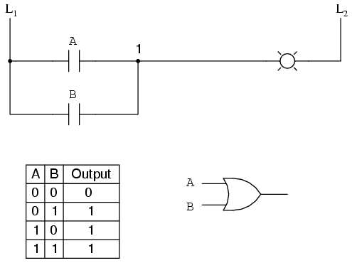
Now, the lamp will come on if either contact A or contact B is actuated, because all it takes for the lamp to be energized is to have at least one path for current from wire L1 to wire 1. What we have is a simple OR logic function, implemented with nothing more than contacts and a lamp.
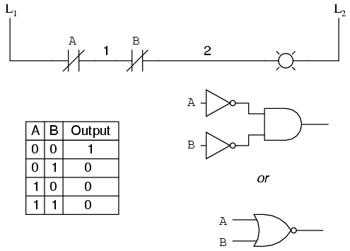
We can mimic the AND logic function by wiring the two contacts in series instead of parallel:

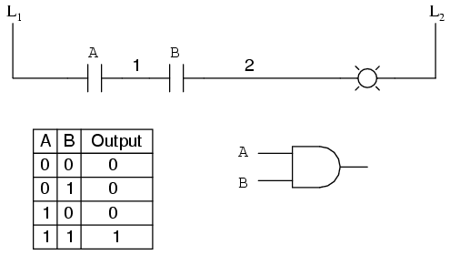
Now, the lamp energizes only if contact A and contact B are simultaneously actuated. A path exists for current from wire L1 to the lamp (wire 2) if and only if both switch contacts are closed.
The logical inversion, or NOT, function can be performed on a contact input simply by using a normally-closed contact instead of a normally-open contact:

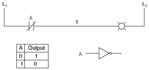
Now, the lamp energizes if the contact is not actuated, and de-energizes when the contact isactuated.

If we take our OR function and invert each "input" through the use of normally-closed contacts, we will end up with a NAND function. In a special branch of mathematics known as Boolean algebra, this effect of gate function identity changing with the inversion of input signals is described byDeMorgan's Theorem, a subject to be explored in more detail in a later chapter.

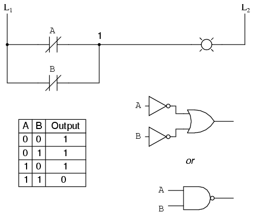
The lamp will be energized if either contact is unactuated. It will go out only if both contacts are actuated simultaneously.
Likewise, if we take our AND function and invert each "input" through the use of normally-closed contacts, we will end up with a NOR function:


A pattern quickly reveals itself when ladder circuits are compared with their logic gate counterparts:
  • Parallel contacts are equivalent to an OR gate.
  • Series contacts are equivalent to an AND gate.
  • Normally-closed contacts are equivalent to a NOT gate (inverter).
We can build combinational logic functions by grouping contacts in series-parallel arrangements, as well. In the following example, we have an Exclusive-OR function built from a combination of AND, OR, and inverter (NOT) gates:

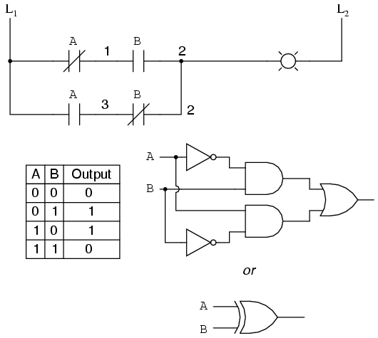
The top rung (NC contact A in series with NO contact B) is the equivalent of the top NOT/AND gate combination. The bottom rung (NO contact A in series with NC contact B) is the equivalent of the bottom NOT/AND gate combination. The parallel connection between the two rungs at wire number 2 forms the equivalent of the OR gate, in allowing either rung 1 or rung 2 to energize the lamp.
To make the Exclusive-OR function, we had to use two contacts per input: one for direct input and the other for "inverted" input. The two "A" contacts are physically actuated by the same mechanism, as are the two "B" contacts. The common association between contacts is denoted by the label of the contact. There is no limit to how many contacts per switch can be represented in a ladder diagram, as each new contact on any switch or relay (either normally-open or normally-closed) used in the diagram is simply marked with the same label.
Sometimes, multiple contacts on a single switch (or relay) are designated by a compound labels, such as "A-1" and "A-2" instead of two "A" labels. This may be especially useful if you want to specifically designate which set of contacts on each switch or relay is being used for which part of a circuit. For simplicity's sake, I'll refrain from such elaborate labeling in this lesson. If you see a common label for multiple contacts, you know those contacts are all actuated by the same mechanism.
If we wish to invert the output of any switch-generated logic function, we must use a relay with a normally-closed contact. For instance, if we want to energize a load based on the inverse, or NOT, of a normally-open contact, we could do this:

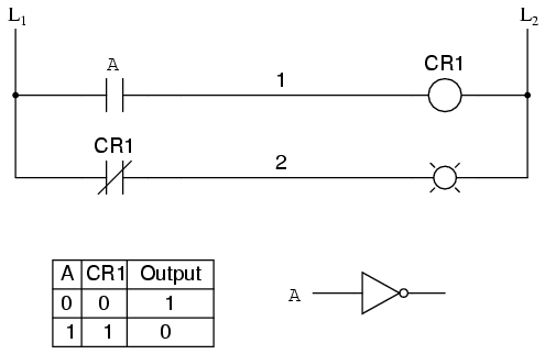
We will call the relay, "control relay 1," or CR1. When the coil of CR1 (symbolized with the pair of parentheses on the first rung) is energized, the contact on the second rung opens, thus de-energizing the lamp. From switch A to the coil of CR1, the logic function is noninverted. The normally-closed contact actuated by relay coil CR1 provides a logical inverter function to drive the lamp opposite that of the switch's actuation status.
Applying this inversion strategy to one of our inverted-input functions created earlier, such as the OR-to-NAND, we can invert the output with a relay to create a noninverted function:

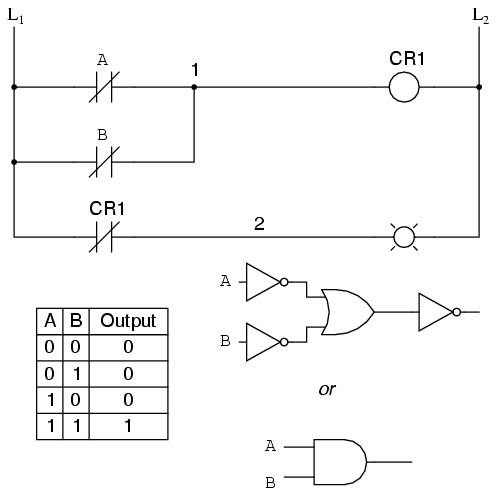
From the switches to the coil of CR1, the logical function is that of a NAND gate. CR1's normally-closed contact provides one final inversion to turn the NAND function into an AND function.
Pratik Solanki (09067675187)